Radio Frequency Communications
Written by Wyatt Melin on 10/30/22
We've all experienced this issue before: "What's the password to the WiFi?" Or perhaps you have funny neighbors like me who have amusing SSID names like "pretty fly for a WiFi" (a personal favorite of mine). Does this sound familiar? Regardless of the wireless transmission method, all we really care about is being connected to the internet - that's it! But how are these signals actually propagated? Is there a magical chamber in every system where Gandalf uses his powerful wizardry to produce the signal? Did I land the Lord of the Rings joke?
In this post, I will demystify concepts such as the general electromagnetic spectrum, radio frequency communications, RF circuits, and modulation. By the end of this article, you should have a better understanding of how all of these things work!
Electromagnetic spectrum
In physics, electromagnetic radiation consists of waves in the electromagnetic field that propagate through space and carry electromagnetic energy. This includes radio waves, microwaves, infrared, ultraviolet, X-rays, and gamma rays. All of these rays are part of what is called the electromagnetic spectrum. Even if this is the first time you've heard of the electromagnetic spectrum, you experience it every day! The basic idea behind the electromagnetic spectrum is simply a range of all types of electromagnetic radiation, based on their frequency and wavelength.
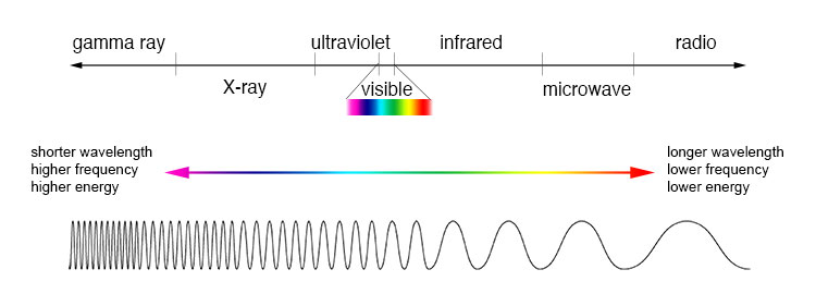 Measuring electromagnetic radiation. Source: https://imagine.gsfc.nasa.gov/science/toolbox/emspectrum1.html
We humans are familiar with the visible spectrum segment of the electromagnetic spectrum because it's what the human eye can see. Typically, the human eye can detect wavelengths from 380 to 700 nanometers. If we move away from the visible spectrum to higher frequencies, we notice that higher frequencies have shorter wavelengths. Similarly, lower frequencies have longer wavelengths. You might be thinking, "I came to this article to learn about radio signals, and so far, it's talking about wavelengths. What gives?" Well, I'm glad you asked!
Before encoding information on the electromagnetic spectrum, we need to choose a frequency to communicate with. Choosing the frequency will have an impact of the type of the antenna design choice. The next question becomes, what frequency to choose? Higher frequencies (Gamma Ray, X-ray, Ultraviolet) are dangerous to humans and should not be used for electronic communication. Radio waves, microwaves and infrared should be used for electronic radio communication.
At this point, we know a little bit about the electromagnetic spectrum and what type of frequencies we can use to encode an electronic radio frequency. You might be thinking that infrared has the higher frequency and therefore better architecture, right? Not so fast, pal - we live in a world of tradeoffs! Higher frequencies have shorter wavelengths and behave more like light, which is great if you want your signal to be more focused. But one tradeoff with higher frequencies is that they experience more atmospheric attenuation than lower frequencies. NASA has a good diagram that illustrates this point.
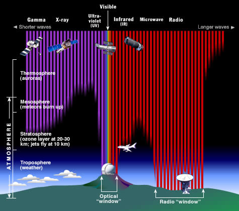 Earths atmosphere. The Earth's atmosphere stops most types of electromagnetic radiation from space from reaching Earth's surface. This illustration shows how far into the atmosphere different parts of the EM spectrum can go before being absorbed. Only portions of radio and visible light reach the surface. (Credit: STScI/JHU/NASA) Source: https://imagine.gsfc.nasa.gov/science/toolbox/emspectrum1.html
What's interesting about this diagram is that you can see that gamma ray, X-ray, and ultraviolet rays are blocked by the Earth's atmosphere. Fascinating, right? As you can see, there's a "radio window" of radio frequencies that reach space if you need to communicate with something up there! What's also nice about lower frequencies is that they can penetrate objects like the ground or water.
Well done! At this point, I wouldn't blame you if you stopped reading and grabbed a beverage of your choice. It's a lot of information! But buckle up, because the next part gets even more interesting! I'll talk about how to modulate and demodulate a signal so we can use the electromagnetic spectrum to encode information with electronics.
Rf Transmitter Architecture
There are 4 electrical components that make up what are called RF circuits. These components are Resistor, Oscillator, Filter, and Amplifier. We assemble these components together into what is called the “RF Transmitter Architecture.” The goal with the RF transmitter architecture is to take data as input (1’s and 0’s) and output a fluctuating magnetic field that propagates out and can be received by a remote receiver.
Let’s look at a diagram of a transmitter and receiver in an LTE device. Let’s start with the TX signal (transmission signal). In this diagram, digital data is funneled in from the “DigiRF interface” and passed to the DAC (Digital to analog conversion). This analog signal is than passed into the IQ modulation, where the signal converts the information into RF signals. You might ask, why do we need to upconvert the analog signal? It turns out you can build cheaper RF circuits if you use lower frequencies. Extending from the IQ modulation, you can see PLL (phased lock loop) synchronizer to synchronize the signals to find the proportional difference between the two signals. Finally, we then take the output of that and feed into what’s called the power amplifier, which is finally sent out over the antenna.
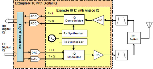 Simplified block diagram of transmitter and receiver in an LTE device. Source: https://www.microwavejournal.com/articles/print/9158-real-world-stimulus-response-testing-for-lte-transmitter-rf-components
As you might expect, the RX (receive signal) is following much the same process as TX. Except in reverse. It starts with the signal from the antenna feeding data into LNA (Low Noise Amplifier), the signal then steps into IQ demodulation phase. Post downconversion, it then demodulates from analog to digital!
Modulation
Ok, up until this point, we understand the general idea behind the RF architecture, its purpose, and some high-level hardware functions that happen both on the RX and TX. But how do we go about modulating the signal? What exactly is the process behind encoding bits into wireless data? Let us first understand the need for modulation. The basic intuition behind modulation is to superimpose a low-frequency message with a higher frequency carrier signal so it can be transmitted over long distances. It turns out that the frequency of the signal matters for reasons such as length of antenna, narrow banding of signal, frequency multiplexing and effective power radiated by the antenna. For example, the human voice is concentrated around 300 Hz. We can formally express the antenna length to transmit the human voice:
λ = c/f
c is the speed of voice ( 3 × 10⁸ m/s )
f = 300 Hz
λ = 3 × 10⁸ / 300
λ = 1000000 m
λ = 1000000 m / 1000
λ = 1000 km
Which means we need an antenna size of 1000km to transmit 300 Hz frequency! Hopefully this draws out the need for modulation!
There are three methods to do modulation. They are Amplitude Shift Keying (ASK), Frequency Shift Keying (FSK), Phase Shift Keying (PSK). These 3 keying modulations schemes mentioned have one thing in common, they make frequency changes to what’s called a carrier signal. A carrier signal is a waveform that modulated with an information-bearing signal for the purpose of conveying information. If you are a music nerd like me, carrier signals can also be used in music production by modulating a signal to change the sound property of an audio recording! Which adds a sense of depth and movement!
A carrier signal can be formally expressed by:
Ac cos(2π fc t + φc) Where:
Ac = amplitude (ASK)
fc = frequency (FSK)
φc = phase (PSK)
Basically, if we vary the amplitude, we call that amplitude shift keying (ASK). If we vary the signal between 2 different frequencies, we call that frequency shift keying (FSK). If we vary the phase between 2 different values, we get phase shift keying (PSK).
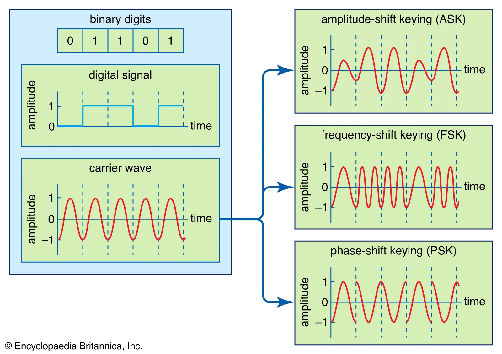 A digital signal, representing the binary digits 0 and 1 by a series of on and off amplitudes, is impressed onto an analog carrier wave of constant amplitude and frequency. In amplitude-shift keying (ASK), the modulated wave represents the series of bits by shifting abruptly between high and low amplitude. In frequency-shift keying (FSK), the bit stream is represented by shifts between two frequencies. In phase-shift keying (PSK), amplitude and frequency remain constant, and the bit stream is represented by shifts in the phase of the modulated signal. Source: https://www.britannica.com/technology/modulation-communications